
Power analysis based software reverse engineering assisted by fuzzing I
26. August, 2019
This is the first part of a three part series about power analysis based software reverse engineering. It is part of our work in the SecForCARs project and the bachelor thesis “Poweranalyse basiertes Software Reverse Engineering mit Hilfe von Fuzzing”. The results will be summarized in this blogpost series. In this first part the goals of the research and the power analysis template extraction process are presented.
The following list shows the topics of all scheduled blog posts. It will be updated with the corresponding links once new posts are being released:
- Goalsandtemplateextractionprocess
- Templateanalysisandreverseengineering
- Fuzzing based on reconstructed flow
Concept
Every modern dishwasher, car or fabrication machine contains at least one embedded microcontroller. Those controllers receive commands and data from sensors or other embedded systems and also control electronic actuators. Due to intellectual property reasons or to protect the functionality of the devices itself, the firmware running on embedded microcontrollers is in many cases not accessible (e.g. via the controllers debugging interface). This is an unfortunate situation for security research. To bypass the security mechanisms of such embedded systems, and gain insight into the firmware, so called “side channel attacks” can be used. Side channel attacks use physical properties of a targeted system to attack it.
When it comes to microcontrollers, processor pipelines are much simpler than on regular computers. They execute instructions in the program given order, in contradiction to super scalar desktop and server processors which can reschedule instructions for better utilization of their execution units. When an instruction is executed on such a microcontroller, the power consumption can change during this execution depending on what kind of operations are performed and on which execution unit of the processor. This can leave a characteristic pattern on the power trace of the microcontroller. A recording of a characteristic power trace for a specific instruction is later referred as “template”. Such a template can be correlated with any recorded power trace to detect when the corresponding instruction is executed. With that information the program’s execution flow graph can be reconstructed. This graph can then be used to reassemble parts of the executed program.
Under normal circumstances the target processor can not be used to run test programs to record a template of a specific instruction, since the researcher has no access to the processor. But if the templates of two processors of the same type are interchangeable the templates can be recorded on a separate microcontroller. This leaves another problem: A software that mostly reacts to external inputs is idle most of the time. Even when, an input is triggered only a small part of the program becomes active. To maximize the executed code a computer with a fuzzer that feeds a big variety of messages to the controller can be attached.
This allows an attack of the following scenario:
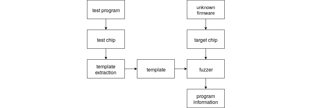
Templates for all instructions are created with a separate microcontroller of the same type as the target controller. Those templates can be correlated with the recorded power consumption of the target after a specific input over a peripheral bus. The resulting information can then be used by a fuzzer attached to the peripheral bus to optimize its input. It uses the reconstructed execution flows to check if the same behavior was triggered from different inputs. If the same behavior was triggered, different messages will be send to the microcontroller.
Target and setup
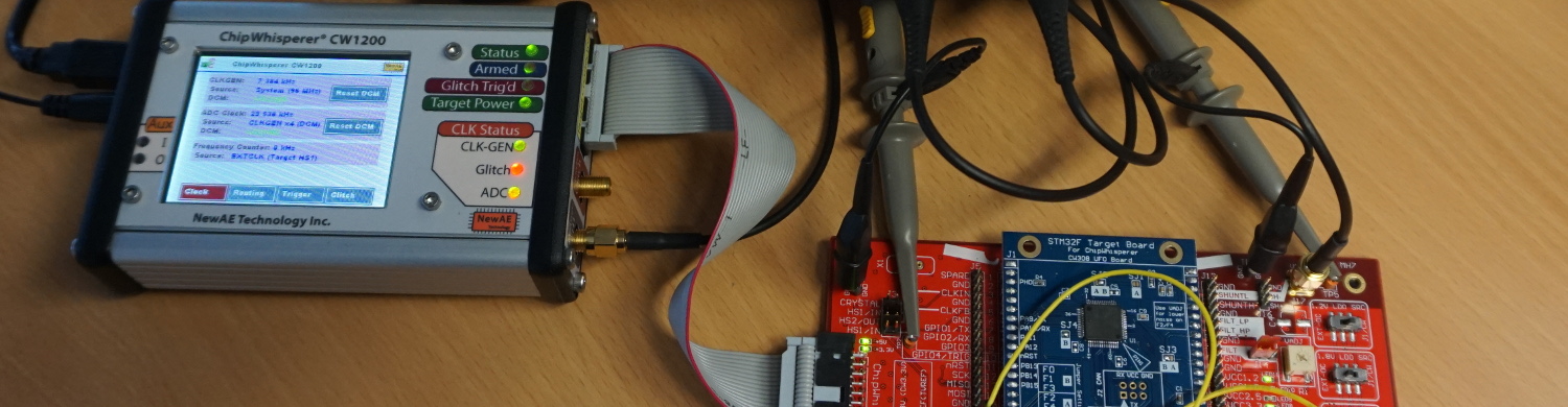
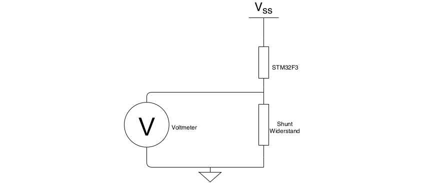
In our research the STM32F3 was chosen as a target, because it is a widely used chip which has an included ARM Coretex M4, voltage regulator and a lot of peripheral interfaces like SPI, I2C and CAN. To perform the power analysis we used a Chipwhisperer-Pro and a Picoscope , providing a Python software interface and a high enough sample rate to analyze the power trace of the STM32F3. To measure the current draw of the microcontroller the voltage across a shunt resistor on the power input of the STM32F3 is connected to the Picoscope or the Chipwhisperer.
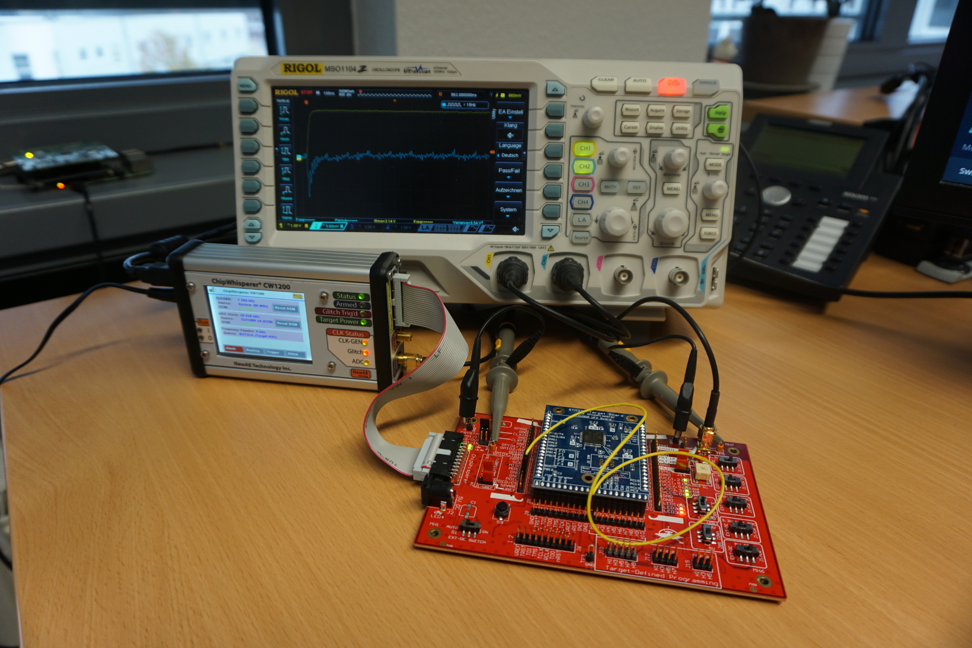
The test setup consists of a ChipWhisperer CW1200, a Picoscope 5244D, the STM32F3 target board and the UFOBoard . The target board consists of the STM32F3 and a minimal circuitry to run the controller. It is attached to the UFO board which connects the target to the ChipWhisperer and the Picoscope. The Picoscope and the ChipWhisperer are hooked up to GPIO13 and to the shunt resistor. The signal from GPIO13 will be used as a trigger for recording the voltage across the shunt resistor. The ChipWhisperer is primarily used as a fast flasher and clock source for the target but it can also be used as main measurement instrument. But it is more accurate to use the Picoscope which has a better time and voltage resolution. It does not matter what kind of oscilloscope is used as long as its sample rate is 3x faster than the base clock of the STM32F3. For example on the setup depicted above a Rigol oscilloscope was used to check the measured signals of the ChipWhisperer.
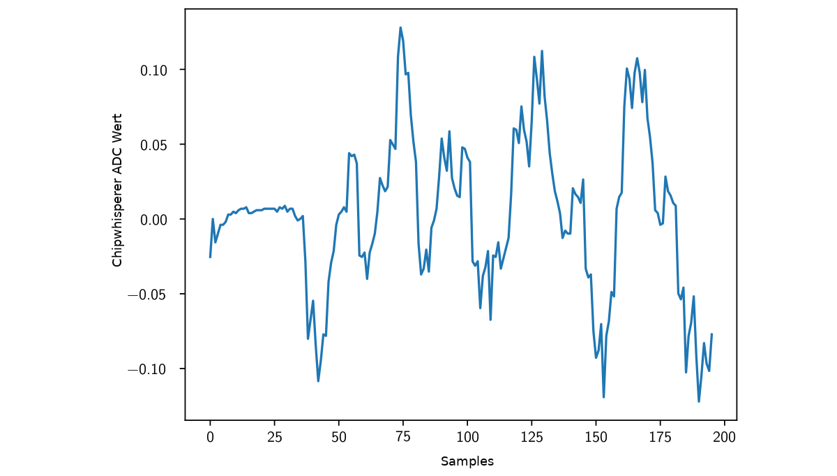
To measure the current draw of one specific instruction a test program that runs the instruction has to be created, flashed and executed on the microcontroller. It is important to record as little as possible because long recordings make it difficult to find the piece of the recording that actually represents one specific instruction. This can be achieved by changing the state of a GPIO from LOW to HIGH right before the instruction is executed. The state change of the pin triggers the oscilloscope to record and after the instruction a second state change can be used to trim the end of the recording.
But even inside the boundaries of the trigger signals the instruction’s power trace is padded with parts of the function return of the pin set and the stack restore. To separate those from the actual instruction further analysis is necessary.
Extraction of the Templates
In order to extract a template of a specific instruction a series of tests must be recorded. The tests are chains of the same instruction in different lengths.
If for example a chain with two repetitions is subtracted from a chain with three repetitions the first two repetitions cancel out each other and it is noticeable when the third repetition starts. It is even more visible and better detectable if the signal is filtered with a 50% threshold filter.
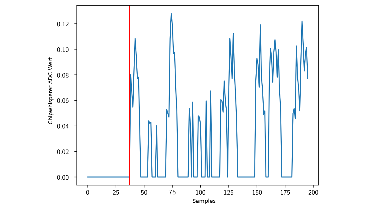
When the signal is above zero for the first time the third repetition starts. To detect the end of the third repetition the chain with three repetitions is subtracted from a chain with four repetitions. The first difference is the beginning of the fourth repetition and the end of the third.
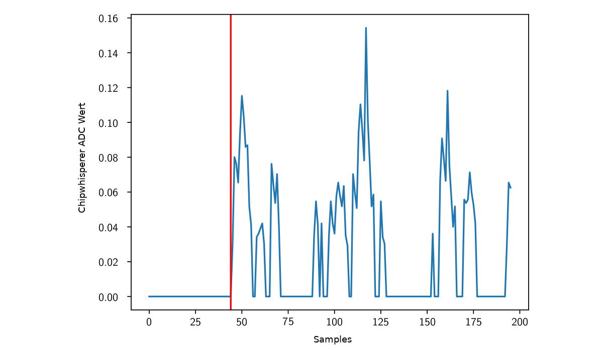
The resulting start and end points can then be used to cut out the actual template from the three repetition recordings.
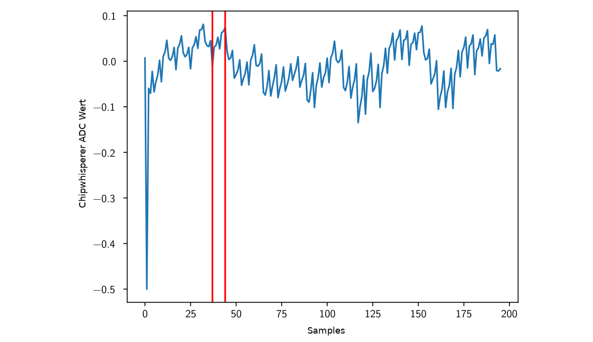
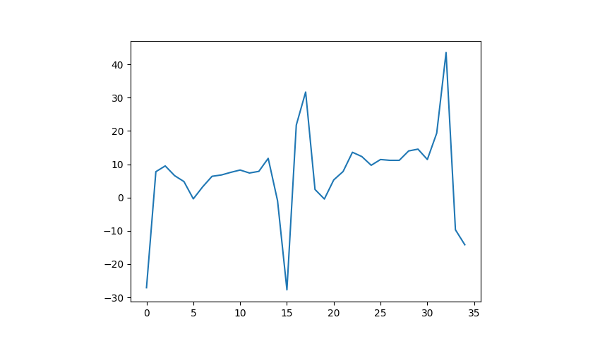
This is the final template of a “add r0, r0” instruction:
Next Post
Continue reading the next part of this series in which we will analyze the templates used to reconstruct programs here .
References / Credits
The work was sponsored by the BMBF project SecForCARs and created at SCHUTZWERKGmbH (supervisor Dr. Bastian Könings & Msc. Heiko Ehret) in cooperation with the InstituteofDistributedSystems at Ulm University (referee: Prof. Dr. Frank Kargl, supervisor Dr. Rens van der Heijden).